King Pin

King & Link Pin

Ken on King Pins ....... (and other Wobbly bits!!)

- an extract from The Historic Volkswagen Issue IV 1998 - by Ken Cservenka one of our Technical Advisors.

Editors Note:- We notice there are large number of hits to this page, so please email Webmaster to let us know your reasons for visiting and if we can help by providing more information on this subject.

In my last article I described the procedure for the replacement and adjustment of the wheel bearings. However, even when the wheel bearings are correctly adjusted there is still some movement when you rock the wheel by firmly pushing at the top and bottom. This play could be either the link pins or king pins.

The link pins or stub axle mounting pins are the horizontal pins which hold the torsion arm link and stub axle assembly to the torsion arms. The king or swivel pins are the vertical pins which hold the stub axle to the torsion arm link and allow the stub axle to swivel when the steering is turned.


Click on image to expand view.

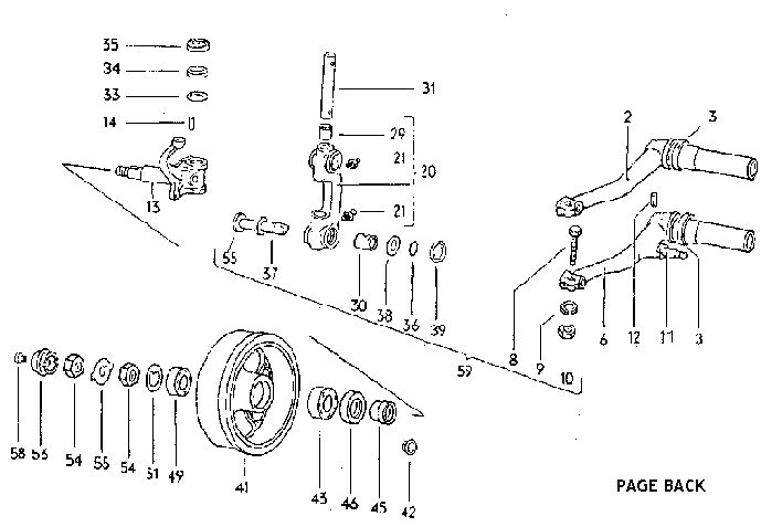
The link pins have a helical groove in their shaft, which engages with the pinch bolts that hold the torsion arm link assembly to the torsion arms. This allows adjustment to eliminate play. Before attempting to adjust the link pins clean off any hard grease, or road dirt, that may have accumulated and pump grease into the two grease nipples until fresh grease oozes out of the joints.

Adjustment of VW Beetle front suspension Link-Pins.

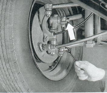
To adjust the link pins slacken the pinch bolts located at the end of the torsion arms and with a spanner, on the flats at the end of the link pins, fully tighten. Then slacken the adjustment about one eighth of a turn and finally tighten gently until the play is eliminated. Do not over-tighten at this stage, or the suspension may bind. When you are satisfied with the adjustment tighten the pinch bolts.  Repeat the adjustment procedure for each link pin.  If the shims each side of the torsion arm link are badly worn it will not be possible to eliminate the play. In this case the shims would need to be replaced.

If there is still movement when you rock the wheel after adjustment, get an assistant to look at the joint at the top and bottom of the stub axle, where it fits into the torsion arm link. If movement can be detected here the king pins will need replacing. The link pins will also need replacing as their bushes have to be removed before the king pins can be removed.

To replace the king pins and link pins remove the wheel and brake drums, following the procedure set out in The Historic VW 1'98 entitled, 'Ken C on Wheel Bearings'.

Have two lengths of strong string, or wire handy and then remove the three bolts holding the brake backplate onto the stub axle. These are sometimes secured after tightening with locking wire. Tie the backplate up, so as not to strain the brake hose, or brake cable.

Remove the split pin and nut from the outer track rod end, before using a ball joint splitter to disconnect the ball joint from the stub axle assembly. Remove the pinch bolts, holding the link pins to the torsion arms and using a soft faced hammer, or mallet, hit the torsion arm link to drive out the pins equally.

Using a large vice, press the link pin bushes out of the torsion arm link. You will need a socket slightly smaller than the bush and a piece of pipe slightly larger to push the bush into.

To remove the king pin heat the torsion arm link assembly in an oil bath. A camping stove and an old saucepan is ideal, as it makes quite a smell to do it in the kitchen.

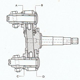
Take care as hot oil can be very dangerous. Heat the assembly to 80 degrees centigrade (175 F) for at least 1/2 an hour. Do not overheat the oil. Press out the king pin, or use an improvised punch, such as an extension bar from a socket set. When the king pin has been removed the stub axle can be separated from the torsion arm link. Press out the bronze king pin bushes.

To reassemble press the new bronze king pin bushes into the torsion arm link. These are pressed in from the inside to the outside of the link. After fitting, you will need to file notches in the upper bush, to match the notches in the torsion arm link. These are to locate the thrust washer cover plate.

Now for the technical bit! The king pin bushes need to be reamed to the exact diameter of the king pin. To do this you will need an adjustable parallel reamer and guide, with a range between 18 and 21 mm diameter. The tapered guide acts as a bush and is located in the opposite bush to the one being reamed. Ream the bushes a little at a time, making very small adjustments to the reamer, until the king pin can be fitted to the bushes with no detectable play.

The next stage is to check the stub axle, which should be replaced if the steering arm is bent. You should not attempt to straighten a bent steering arm. Next check that the wheel bearing race seating surface on the stub axle is not worn. Also check the seating surface for the king pin thrust washer and remove any burrs. Finally check that the thrust washer dowel is a tight fit in the stub axle.

In the new king pin kit you should have found a new fibre, or plastic, washer, plus a cover, which you use in conjunction with the steel thrust washer you removed during disassembly. VW Front Stub axle section view. Pre March 1960 version.

The stub axle assembled with the steel thrust washer, fibre washer and cover should be either a dead fit, without any play, or with a maximum of : .02mm pre-load. On older cars, without a steering damper fitted, the pre-load should be between .03mm and .07mm. By pre-load I mean the parts are thicker than the gap they are fitted into. Thrust washers are available in sizes from 3.56mm to 4.30mm.

Next place the well oiled king pin in a plastic bag in the freezer and heat the stub axle alone in the oil bath, with the king pin end immersed. When you are sure it has been heated to 80c (175f) place the the torsion arm link upright in the vice and with the thrust washer, fibre washer and cover in place on the hot stub axle, fit them into the torsion arm link. Align the bushes in the torsion arm link, with the hole in the stub axle and drive in the king pin.

Press the link pin bushes into the torsion arm link, ensuring that the oil passages are correctly aligned. Some manuals suggest heating the bushes for 24 hours before fitting, but the original VW manual of 1960 does not mention it. Ensure that the link pin bushes do not protrude into the shim recess in the torsion arm link.

Before fitting the torsion arm link assembly, the offset of the torsion arm eyes should be measured. To do this place a steel straight edged rule squarely on the bottom torsion arm eye and measure the distance between the rule and the top eye. The standard measurement should be 7mm, with a permissible deviation of +/- 2mm.

Any deviation from the 7mm is corrected by repositioning the shims which are 0.5mm each. Cars built before March 1960, chassis number 292155, have 10 shims per link pin and after that date 8 shims per link pin, plus a rubber dust excluder and dust excluder retainer.

Example One - Car built prior to March 1960, before chassis number 2921551 with standard 7mm offset. Place five greased shims onto each greased link pin and push pin through torsion arm link. Place five greased shims onto each protruding link pin and assemble onto torsion arm eyes. Insert pinch bolt and adjust link pins as previously outlined.

Example Two - Car built after March 1960, chassis number 2921552, with standard 7mm offset. Place five greased shims on each greased link pin and push pin through torsion arm link. Place three greased shims onto each protruding pin followed by rubber dust excluder and retainer. Assemble as before onto torsion arm eyes. Please refer to the following tables and diagram to correct any deviation to the offset.

Table One - before March 1960 Chassis No. 2 921 551
Offset in mm
Upper Torsion Arm
Lower Torsion Arm
.
Inner Shim
A
Outer Shim
B
Inner Shim
C
Outer Shim
D
5
3
7
7
3
5.5
4
6
7
3
6
4
6
6
4
6.5
5
5
6
4
7
5
5
5
5
7.5
6
4
5
5
8
6
4
4
6
8.5
7
3
4
6
9
7
3
3
7
Table Two - after March 1960 Chassis No. 2 921 552
Offset in mm
Upper Torsion Arm
Lower Torsion Arm
.
Inner Shim
A
Outer Shim
B
Inner Shim
C
Outer Shim
D
5
1
7
5
3
5.5
2
6
5
3
6
2
6
4
4
6.5
3
5
4
4
7
3
5
3
5
7.5
4
4
3
5
8
4
4
2
6
8.5
5
3
2
6
9
5
3
1
7
 If you have measured correctly and arranged the shims according to the above tables, the contact surfaces of the shims and torsion arm eyes should meet simultaneously during re-assembly. Adjust link pins as previously outlined and reassemble all the other parts in reverse order to the removal sequence. As you have replaced a major part of the steering, it is extremely important to check and adjust the toe in, or tracking. Most large tyre depots check the tracking free and only charge if they need to adjust it.

Part Numbers ......
King pins repair kit - 111 498 021
Link pin repair kit to chassis No 2921551 - 111 498 051
Link pin repair kit chassis No 2921552  to 115 999 000 - 111 498 051 A (VAG £23 + VAT){1998 price}
King pin thrust washers
3.56mm 111 405 486A     3.88mm 111 405 492A
3.63mm 111 405 487A     3.93mm 111 405 493A
3.68mm 111 405 488A     3.98mm 111 405 494A
3.73mm 111 405 489A     4.03mm 111 405 495A   Availability of all, unknown
3.78mm 111 405 490A     4.08mm 111 405 496A
3.83mm 111 405 491A     4.30mm 111 405 497
Share by: