FAN HOUSING
In response to a members query, this item is reproduced from a 1955 workshop manual, hence some of the terms may seem a little old-fashioned. The editor has rearranged things slightly to fit the new website layout.
1. Removal and Installing Fan Housing
(engine removed)
Removal
1. Remove fan belt.
1. Remove fan belt.
2. Remove generator strap and disconnect cable from ignition
coil.
3. Release slotted screws on both sides of fan housing.
4. Detach spring of automatic cooling air control and
release throttle ring screws.
5. Lift off fan housing and generator
Installation
Installing is a reversal of the preceding operation, but the following points should be noted.
1. Examine fan housing for damage and loose air deflector plates2. There must be no "blow-past" between fan housing and cover
plates of cylinders. If necessary, bend plates into correct
position
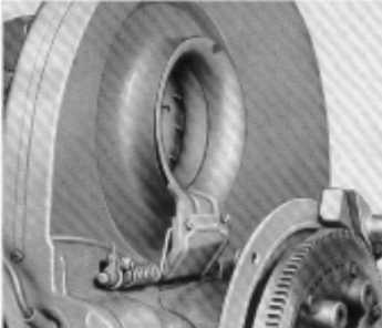
3. Insert throttle ring and screw it to the holding plate on the
operating shaft, taking care that there is no offset between the
intake flange and the throttle ring. The throttle ring is designed
to occupy a tilted position.
-- as seen from the side and from above --
4. and no attempt should be made to bend the holding plate as
such practice would result in a malfunctioning of the cooling
system. The throttle ring is centered to the intake flange by
moving it in its clearance holes.
5. Connect return spring
6. Adjust throttle ring
2. Removal and Installing Fan Housing
(engine in situ)
Removal
1. Disconnect the battery
1. Disconnect the battery
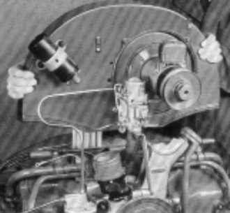
2. Remove rear hood together with hinge bracket.
3. Disconnect cables from generator and ignition coil and
cable from oil pressure switch.
4. Detach and pull out accelerator and choke control cables
and remove conduit tube. The other operations for
removing and installing fan housing are the same as with
the engine removed.
3. Thermostat-Controlled Intake of Cooling Air
Inspection and Adjustment
Adjustment when Assembling Engine
1. Lift thermostat to the upper stop of its support.
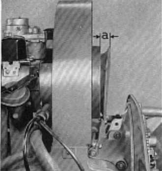
2. Adjust throttle ring so that it opens 20 mm (a - 20 mm /
0.79") as described above.
Regular attention should be paid to the adjustment of the cooling air intake in connection with the routine service. A thorough inspection is especially important when cold or warm seasons begin.
When adjusting the air cooling unit, if should be borne in mind that a premature opening or a permanent 'open' position of the throttle ring are responsible for the engine attaining its operating temperature too slowly. These conditions are most liable to produce incessant carburettor spitting (flat spot) and an increased fuel consumption. If the throttle ring opens too far, it may foul the fan resulting in a considerable noise. A retarded opening of the ring in the warm season creates an excessive heat development when the engine is made subject to sustained high load. If the throttle ring remains 'open' whilst the engine is cold, the thermostat may be defective. To prevent an overheating of the engine, the throttle ring fully opens automatically when the cooling system is out of order.
When adjusting the air cooling unit, if should be borne in mind that a premature opening or a permanent 'open' position of the throttle ring are responsible for the engine attaining its operating temperature too slowly. These conditions are most liable to produce incessant carburettor spitting (flat spot) and an increased fuel consumption. If the throttle ring opens too far, it may foul the fan resulting in a considerable noise. A retarded opening of the ring in the warm season creates an excessive heat development when the engine is made subject to sustained high load. If the throttle ring remains 'open' whilst the engine is cold, the thermostat may be defective. To prevent an overheating of the engine, the throttle ring fully opens automatically when the cooling system is out of order.
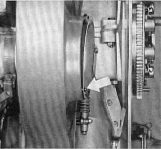
Inspection
1. When the engine is cold, the throttle ring should rest
slightly pre-loaded against the air intake flange.
2. The engine should be allowed to warm up until the upper
2. The engine should be allowed to warm up until the upper
end of the thermostat touches the stop of the support by
the heat expansion (at normal outside temperature).
The distance from the middle of the intake flange to the edge of the throttle ring should measure 20mm (0.79") in this position.
Adjustment when Assembling Engine
1. Lift thermostat to the upper stop of its support.
2. Adjust throttle ring so that it opens 20 mm (a - 20 mm /
0.79") as described above.
3. Tighten operating lever.
4. Tighten thermostat in postion. Be sure the faces milled in
4. Tighten thermostat in postion. Be sure the faces milled in
the tapped boss of the thermostat fit properly in the guide
hole of the support. For this purpose if may become
necessary to rotate the thermostat backward by max. half
a turn. When the thermostat has been tightened, the
throttle ring rests slightly pre-loaded against the intake
flange.
Adjustment with Engine in Car
1. Release throttle ring operating lever.
2. Allow engine to warm up until upper end of thermostat
touches upper stop of the sup- port (at normal outside
temperature).
3. Adjust throttle ring so that it opens 20 mm (0.79").
4. Tighten operating lever.
Make sure that throttle ring and linkage are freely moving in each position.
4. Checking Fan Belt Tension
General Note
Examination
Generator and cooling system are driven by the fan belt. Due to the power absorbed by these two units, the fan belt is subjected to considerable stress, especially at high speed and when shifting down. To insure adequate cooling and long service life of the belt, it is of utmost importance to maintain the belt at correct tension. If the bell is too slack, a slippage occurs between pulley and belt, leading to an overheating of the engine. Excessive tension creates undue stress and is liable to cause breakage of the belt and damage to the generator bearings.
Examination
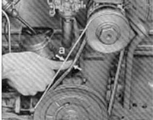
The belt, when pressed with the thumb at mid-point, must yield approximately 15 mm (about 0.6"). No traces of excess use, such as frayed edges and cracks, should be perceptible.
a = 20mm (about 1 in.)
It is important to prevent oil getting on to the fan belt when lubricating the engine.
Oily fan belts can in many cases be made serviceable again by washing them in an alkaline degreasing solution. Fuel must not be used.
Fan belts which have become impregnated with oil are generally unserviceable and must be renewed.
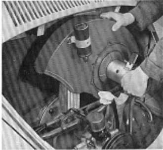
Adjusting Fan Bell Tension
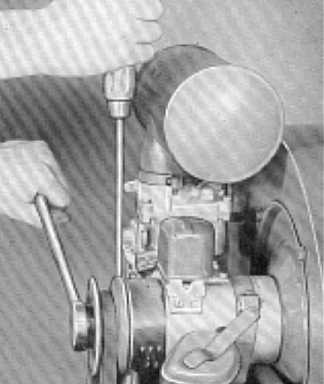
1. Remove nut from generator shaft pulley. When loosening or tightening nut, insert a screwdriver in the slot cut into the inner half of the pulley, and support it against upper generator housing bolt.
2. Remove outer pulley half.
3. Arrange spacer washers as required to correct the fan
belt tension.
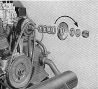
The tension of the fan belt is adjusted by fitting more or less spacer washers between the two pulley halves until the belt yields 20 mm (about 1 in.) by a light thumb pressure. Belt slackness is taken up by removing one or more washers, and if the belt is in too much tension, one or more washers should be added.
Note:
From Chassis No. 1-0 575 41 5 onwards, the fan bell allows a finer adjustment, as, beside the six spacer washers of 1.5 mm (.06") thickness in front of the outer pulley half, there are further 8 washers of 0.5 mm (.02") thickness between the two pulley halves.
When the bell has stretched itself, or is worn, to an extent where no washers remain between the pulleys to obtain the correct tension, the belt is to be renewed, as the amount of cooling air becomes then inadequate due to the reduced number of revolutions of the fan. If is also important that the belt does not bear on the base circle of the pulley, that is, on the washers,
When the bell has stretched itself, or is worn, to an extent where no washers remain between the pulleys to obtain the correct tension, the belt is to be renewed, as the amount of cooling air becomes then inadequate due to the reduced number of revolutions of the fan. If is also important that the belt does not bear on the base circle of the pulley, that is, on the washers,
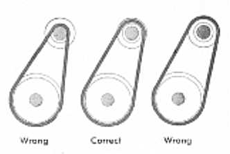
4. Install outer pulley half.
Note:
From Chassis No. 1-0 929 746 onwards, the generator / blower unit is balanced dynamically. To maintain the true running of the balanced unit which safety, the inner half of the generator pulley is welded to the pulley hub. The outer pulley half is held in place by lugs of different widths, allowing a reinstallation in its original position only. The pulley is attached to the generator armature shaft by means of a smaller nut (21 mm wrench).
5. Place all surplus washers between outer pulley half and
pulley nut so that all the spacer washers are retained on
the pulley hub.
6. Tighten pulley nut.
Loose pulleys cause considerable wear and damage to their hubs. The belt is then made subject to excessive wear and tear due to the consequent wobbling of the pulley.
Worn pulleys must be renewed.
Note:
Newly installed fan belts are apt to stretch to some extent and to yield slightly at their flanks, causing belt slackness no later than after the first 50-100 km (30-60 miles). It is, therefore, essential to check the fan belt in time and adjust if necessary.
No attempt should be made to remove the fan bell by means of a screwdriver without backing off the pulley nut, as such practice will destroy the belt and damage the pulley.